

 |
First, we will understand the code, and then we will do a real coding process in a microcontroller using Arduino.

Requirements for this project:
- Arduino UNO
- LED Bulb
- 0.5 K resistor
- Jumper wires or connecting wires
Installing the Arduino UNO:
Let's install the app from the link below:
After you visit this website you can see different options for downloading Arduino in Linux, in Mac, and in Windows. You can choose any of them as per your operating system.
After you click on any of those options you will see 'Just Download' and 'Contribute & Download' option on that page. You can click on the 'Just Download' option and proceed further towards the installation process.
After installation and running the app you will see this window on your computer screen:

The reason behind this pre-populated code blocks is if we don't use loop and setup in our code, our code won't compile. The void keyword is used only for function declaration. The setup() function is basically used to initialize variables, pin modes, etc. The setup() function only runs once, after each powerup or reset of the Arduino board. The code inside the loop() function will run continuously until and unless Arduino is powered off or reset.
Coding:
Erase everything on the screen and write an Arduino code as per your wish. Since this is the tutorial for the blinking LED, here is the code for it:

Let's understand the code and what does each statement in the code represents:
- int pin1=13.....Here we declare variables and int is an integer that reads value as a number. Pin1=13 means digital pin no 13 where we will connect a wire linking bulb and then we will connect bulb with a resistor and in the GND i.e. we will connect a ground pin to the other end of the bulb. Here we have connected resistance so that our bulb will not fuse.
- void setup().....it configures the pin for operation. Like if we have to glow bulb then pin 13 produces an output of 5Volts so that the bulb glows. So it configures pin 13 to produce output that maybe 0 volts or 5 volts since it is a digital pin.
- Are you thinking about input then we will have a detailed discussion in further session when we start learning about sensors and taking values from there.
- void loop()....it means the code will run into the same loop several times. So the void loop runs the program continuously between brackets{...}
- digitalWrite(pin1, HIGH)....it means pin1 i.e. pin no 13 will become high and will receive 5 Volt signal.
- delay(50)....means bulb will glow for 50 milliseconds.
- digitalWrite(pin1, LOW)...means pin 13 will receive 0 volts and the bulb will remain off.
- delay(45)...means bulb will remain off for 45 milliseconds
- now the loop will repeat and again digitalWrite(pin1, HIGH) will be high for 50 milliseconds and the same loop will keep running.
After writing the program hit the tick mark at top of the left side window. That will check if your program is wrong or right. If the program is right then it will show no error and at the bottom of window Done Compiling will appear and you will know "YES YOUR PROGRAM IS CORRECT!"
In this way, the bulb will glow for 50 seconds and turns off for 45seconds. The same pattern will keep running until we change the code. You can bring your own modifications to this code and write in in your own way.
Case Sensitivity:
The above-written code is the language that Arduino or machine understands. So we have to write it in the same way. And the thing to remember in digitalWrite(pin13, HIGH) is here 'W' in digitalWrite is capital and if we write small 'w' i.e. digital write(pin13, LOW) then the computer will not understand. Similarly 'HIGH' should not be written as 'high' it will bring error.
But in place int pin1=13;...instead of pin1 we can write pin or apple or any name as your wish and should use the same name throughout the program for pin configuration of pin no13 if declared earlier.
Uploading our code into Microcontroller:
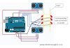
Let's connect the USB to computer and Arduino as shown in the figure below:

Now configure the pin by doing the following process:

Now upload file to Arduino by clicking the icon below:

Always remember that after uploading the file to Arduino then only we will do the connection of bulb and resistors because before uploading there may exist other programs running on Arduino if previously it was used by others and there may be the chances of short circuit.
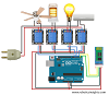
Now remove USB from computer and do the connections as shown in the figure below:

Now connect the USB back to the computer and you will see your first program running on small little brain Arduino in which we taught it to blink bulb for 50 milliseconds ON and 45 milliseconds OFF.
Finally, you made your first microcontroller program and upload it to Arduino and made it blink.
Wasn't it cool and easy??
If you have any query regarding this project you can contact us at nasaelectronics157@gmail.com


1 Comments
Let us know your feedback by commenting
ReplyDeleteIf you have any doubts, Please let us know.